1. Project background
The project is to test and analyze the vibration of a screw compressor unit at the customer's site. The power of the motor is 76kw, and the motor speed is measured at 80Hz (1200rpm) and 100Hz (1500rpm) respectively. The compressor unit operates with variable frequency without loading and unloading. Driving gear 65, low-pressure driven gear 63, high-pressure driven gear 38. Low pressure male rotor 4 teeth, low pressure female rotor 5 teeth, high pressure male rotor 4 teeth, high pressure female rotor 5 teeth.
2. Detailed analysis
2.1 vibration analysis of ge528 screw compressor unit
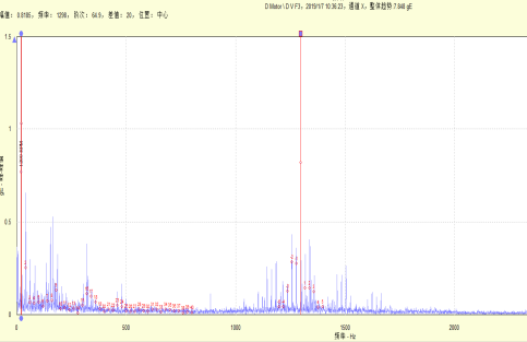
The whole compressor unit has no obvious bearing defect frequency, and the motor side speed spectrum includes rich 1x frequency conversion and frequency doubling signals. The high-frequency acceleration is mainly the meshing frequency (1200rpm, 1300hz) (1500rpm, 1625hz) of the main gear and its frequency doubling 1x frequency side band with the main gear, as shown below:


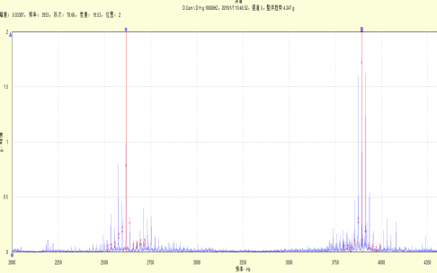
The high frequency of compressor side velocity spectrum including Luo spectrum acceleration mainly includes the meshing frequency (1200rpm, 1300hz) (1500rpm, 1625hz) of the main gear and its frequency doubling 1x frequency conversion sideband with the main gear, as follows:

2.2 summary and suggestions:
1. All bearings of the whole compressor unit have no obvious bearing defect frequency, and the bearings are normal.
2. The speed spectrum of the motor side and the compressor side includes the high frequency of the Luo spectrum acceleration, which is mainly the meshing frequency (1200rpm, 1300hz) (1500rpm, 1625hz) of the main gear (65) and its frequency doubling, and the 1x frequency conversion sideband with the main gear. The noise of the side band compressor unit of the motor and the compressor comes from the wear or poor meshing of the driving gear. It is recommended to check whether the driving gear is in good condition.
3. The main gear is damaged when the customer disassembles it. Based on the confidentiality of the customer, the damaged photos will not be uploaded in this case.
3. Layout of measuring points and measurement direction
The layout of measuring points only describes the general location of each measuring point, which only serves the purpose of condition monitoring. It cannot be equivalent to the assembly drawing of actual equipment. If you want the detailed structure of the monitoring equipment, you need to ask the relevant departments of the factory for the corresponding drawings.
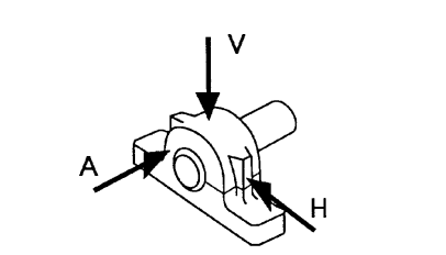
Schematic diagram of measuring points
4. General information
4.1 machine state setting
Green: the machine is in normal state. Perform normal routine maintenance.
Yellow: the machine is in the initial stage of failure or continues to deteriorate, and corresponding maintenance measures need to be taken as soon as possible.
Red: the machine is in a serious fault state and needs to be shut down immediately.
All equipment is divided into five categories according to their status, marked with 1, 2, 3, 4 and 5 respectively, which means:
1. The equipment is in good condition: green.
2. If the equipment has early failure, the equipment can continue to operate: green.
3. If the equipment has obvious faults, the equipment can continue to operate, but patrol inspection or monitoring should be strengthened: yellow.
4. If the equipment has major faults, it is necessary to arrange equipment maintenance as soon as possible: yellow.
5. Stop the machine immediately for maintenance: red.
4.2 machine information and speed
Vibration spectrum analysis is a powerful tool for condition monitoring. However, when the key information of the machine (such as bearing model and manufacturer, coupling type, number of gear teeth, etc.) and speed are unknown, as well as the equipment maintenance history is unknown, the accuracy of spectrum analysis will be greatly weakened. Before collecting vibration data, it is suggested that the factory should tell the necessary information to the data analysis engineers so that they can make more accurate analysis and judgment on the running state of the equipment.
4.4 measurement method
The traditional vibration spectrum analysis method is based on the lower frequency range of 0~2khz. It is usually used to monitor the following mechanical faults: imbalance, misalignment, looseness, shaft bending, etc. Only when the bearing is seriously damaged can the traditional method detect it.
Acceleration envelope technology enhances the energy of repeated high-frequency transient distorted small signals. By combining the acceleration envelope detection technology with the traditional spectrum analysis technology, the early damage and lubrication problems of the bearing can be monitored in time, which can greatly advance the fault warning period of the machine, prolong the service life of the bearing, and prevent sudden shutdown accidents.
4.5 data acquisition interval
It is generally recommended to analyze the equipment failure of the machine at a fixed time interval, partly because of the need to analyze the trend of the machine state, but the more important reason is to avoid the unexpected shutdown of the machine. The length of the time interval should be set according to the criticality of the machine.
(considering the confidentiality of customers, some photos are not easy to upload.)